View Poll Results: 5th Gen LED mod thread, Yepe or Nepe?
I'd read it, maybe even subscribe to it, but I'd never actually have the balls to do it on my car


15.22%


I've already done it, but would like to contribute my experience and technique to this thread


15.22%
Voters: 46. You may not vote on this poll
How to LED your 5th gen _~ Feeler thread .w. POLL


 02-02-2012, 10:27 AM
#46
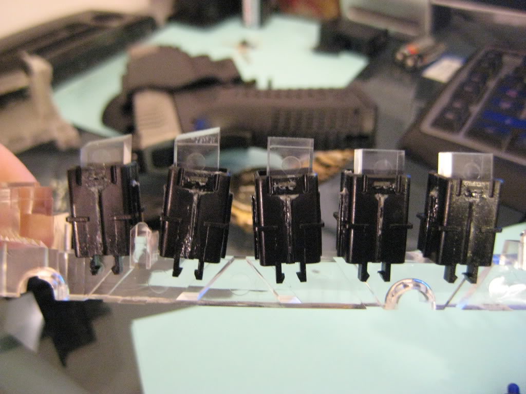
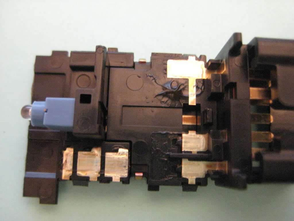
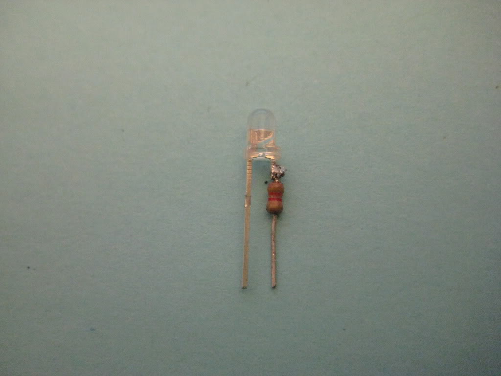
Same Procedure as the others except for the Bending of the leads on picture #8 YOU MUST DO THIS OR THE SWITCH WILL HIT AND SHORT OUT THE LED!.The passenger side rear switch is exactly the same as the drivers side.


02-02-2012, 11:36 AM
#48
I did have it at only about 3/8" off the board at first but when i put it back in the car assembled it was giving a halo effect around the outside of the switch.so i redid it with a longer led without bending it and thats when i found out that the copper contact on the switch would hit both leads of the led when pressed.
 02-02-2012, 12:26 PM
#51
i did that was splashed coffee marks.i tripped getting in the car a few weeks ago and it got everywhere thats when i took the seats and carpet out and used a rug doctor on them.i will never do that again because it was so cold the next 3 days that the carpet froze solid took a whole week to dry completly before i put it back in.
 02-02-2012, 03:55 PM
#55
i need to get the rotary **** off the dimmer to get it out the grooves also.see the yellowish crap on it that stuff dried so bad and hard it wont come off.its on the cluster cover so bad i got it soaking in a bucket of hot water and dish liquid trying to loosen it up.
02-02-2012, 06:11 PM
#56
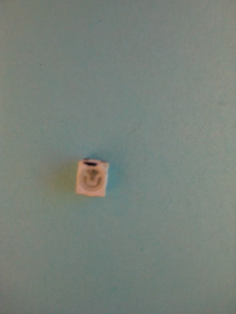
Ok Tuner i ran into my first issue.when i did the dimmer switch it seems that the little lightbulb symbol on the front is just some sort of inlay over a translucent white insert when the light is on it shows thru around the inlay how can i cover this up? some sort of black paint or nail polish because it looks kind of tacky with the bleed thru.also i dont know if you have done a hazzard switch before but what a PITA to put back together.I'm asking this here instead of in pm so that others can see what option and solution there may be.
02-03-2012, 09:50 AM
#57
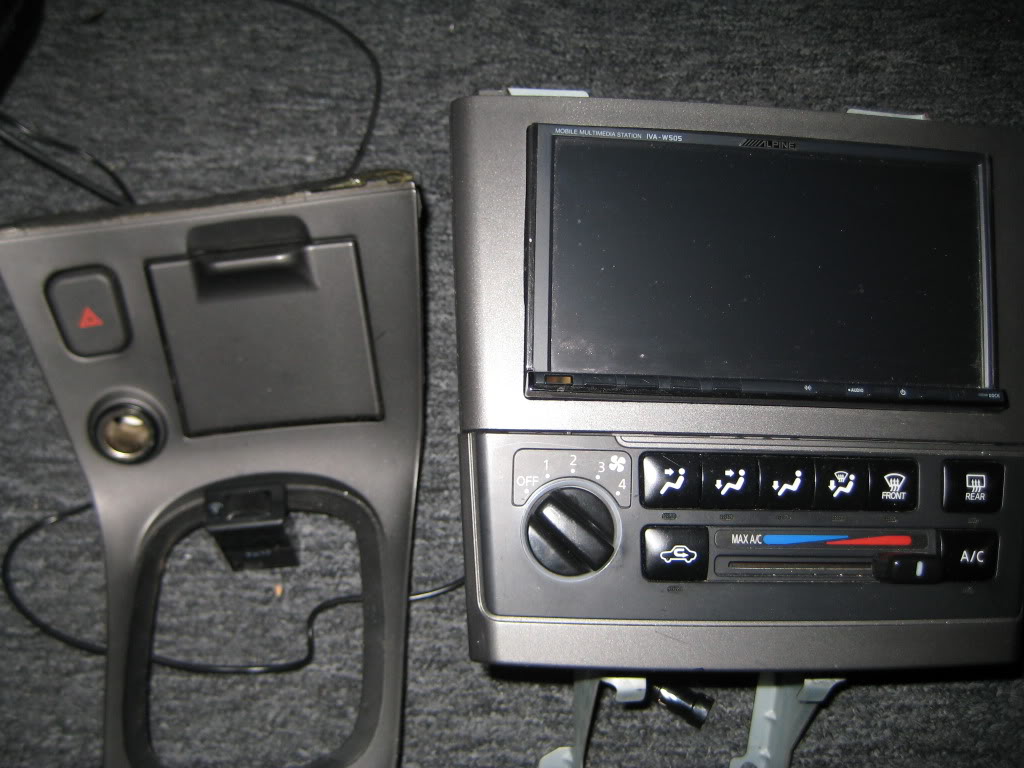
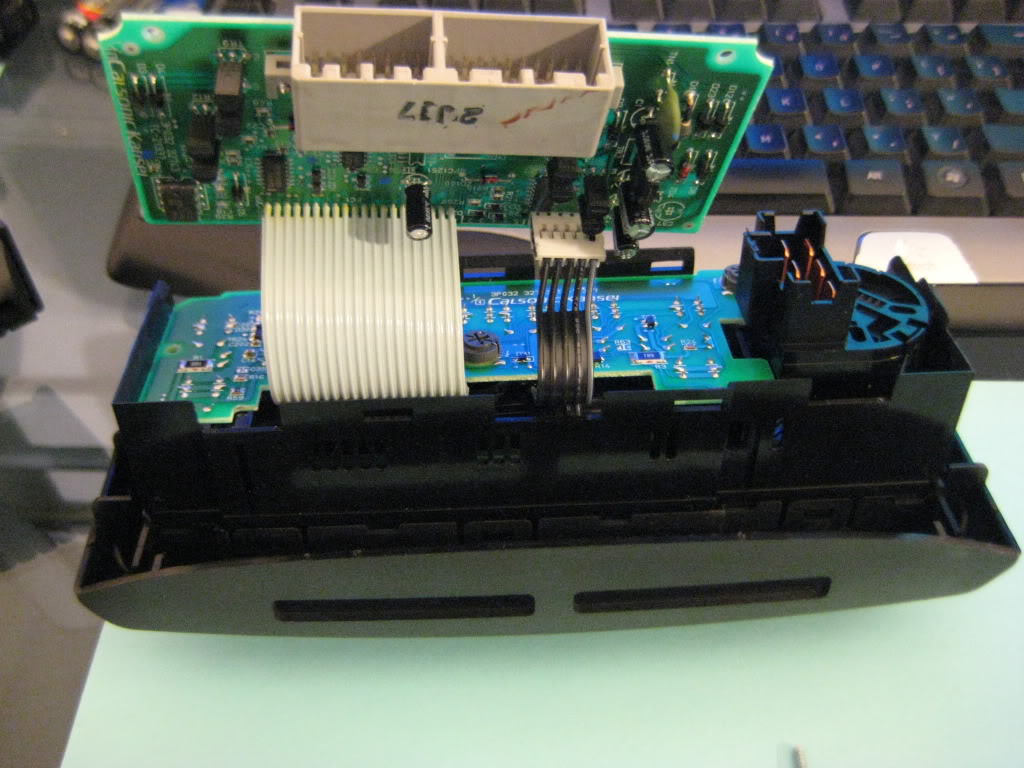
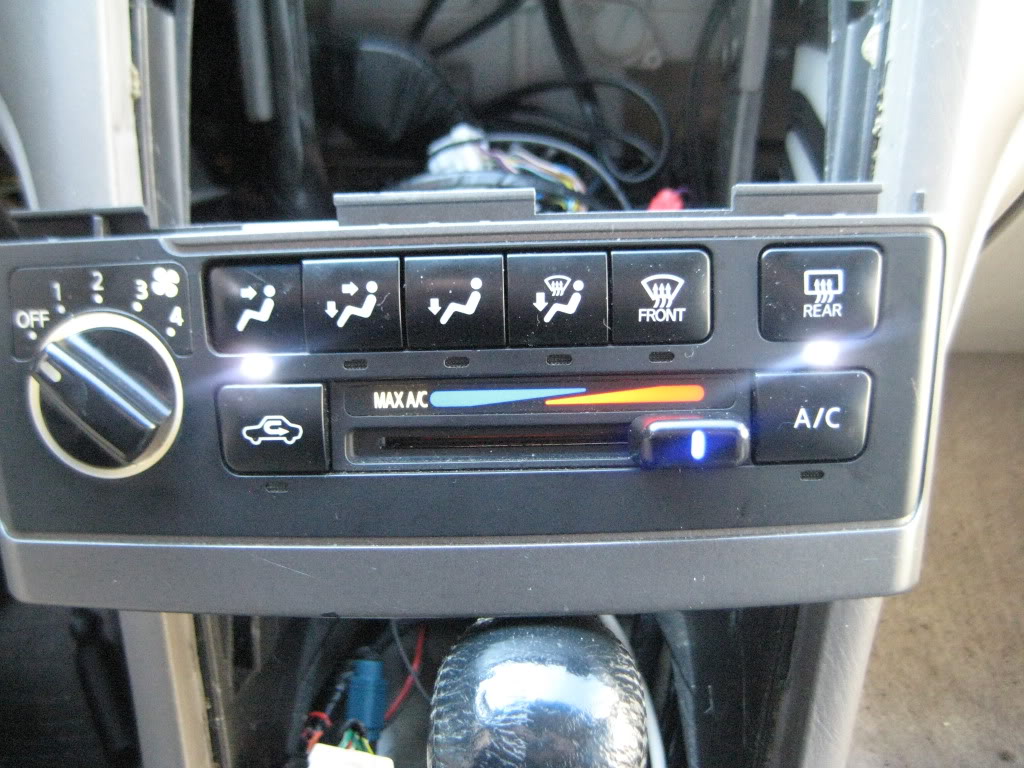
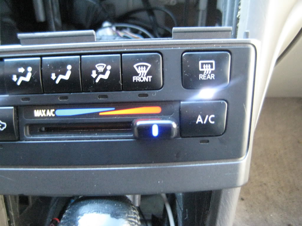
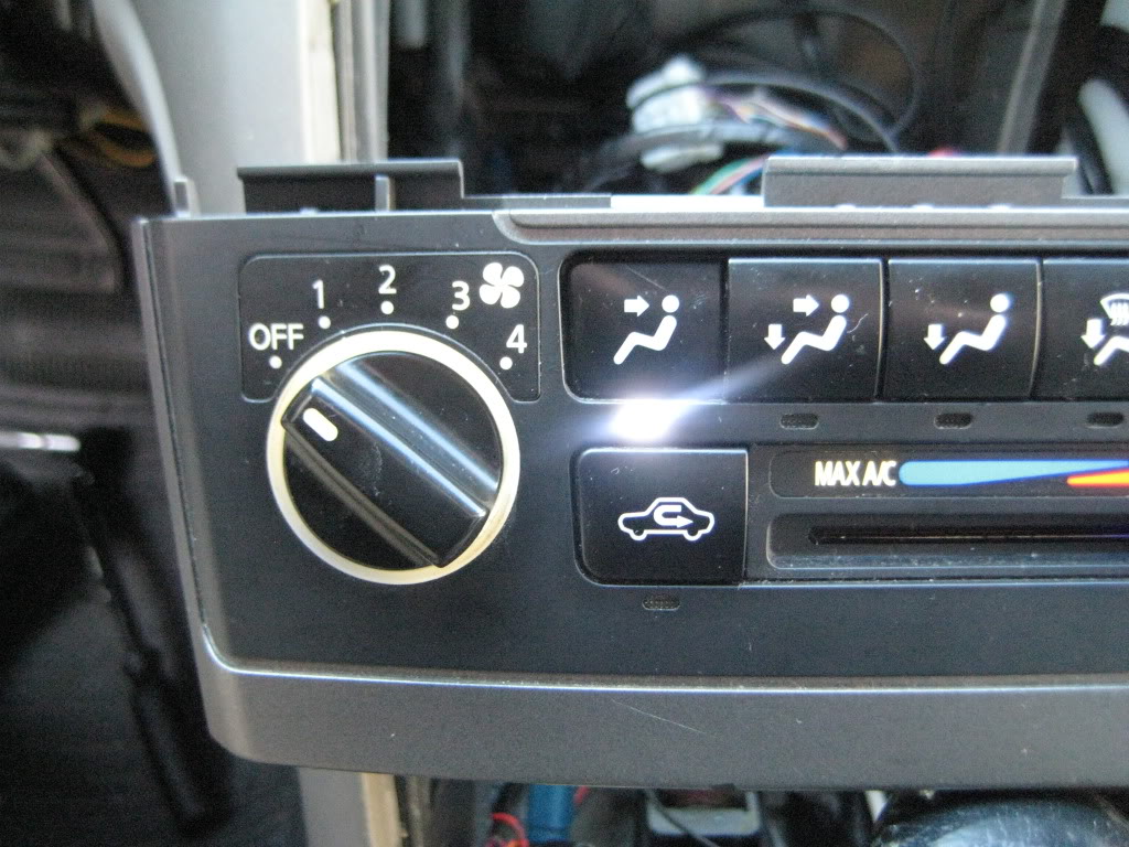
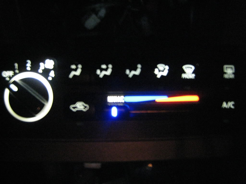
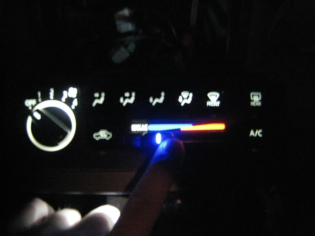
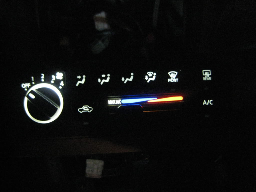
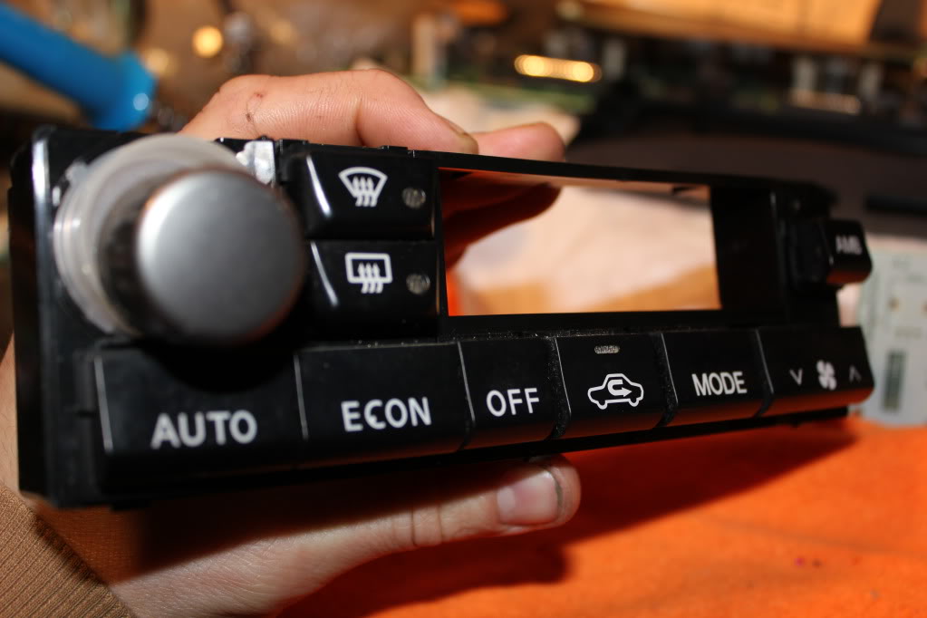
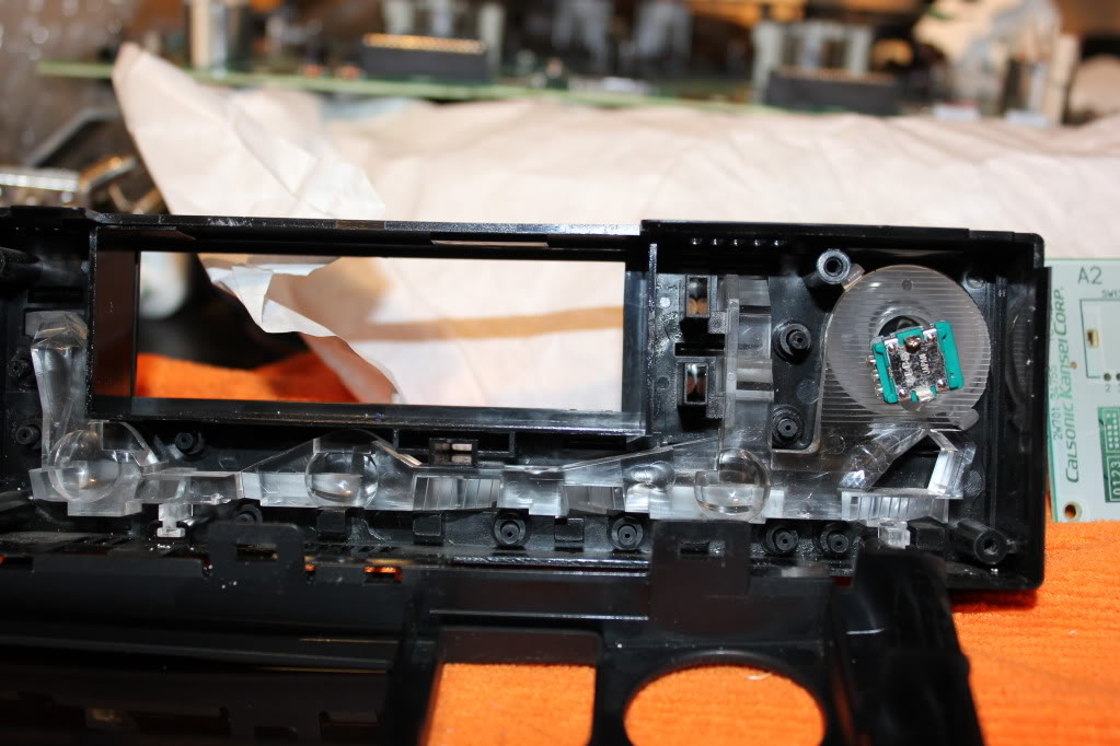
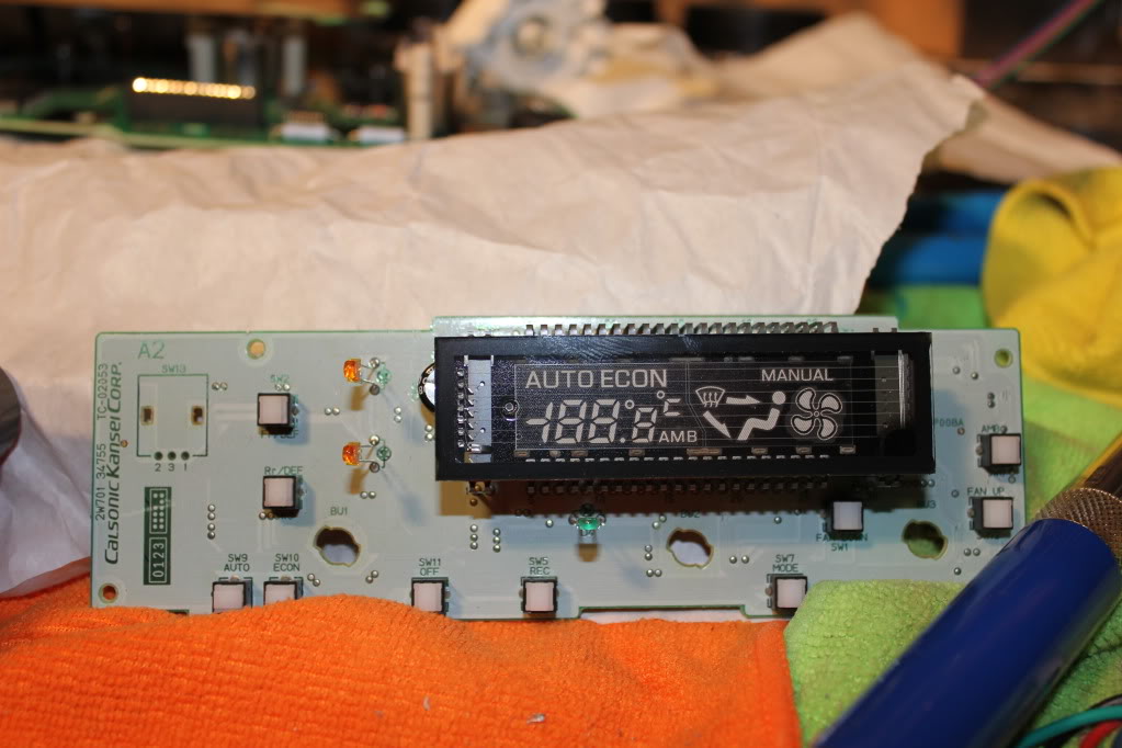
Heater & A/C Controls
Products Used: superbrightleds.com
(8) RL3-W6045 3mm White Led's
(3) NEO4-WHP 4mm Instrument Cluster Led's White
(1) RL-3B2030 3mm Blue Led
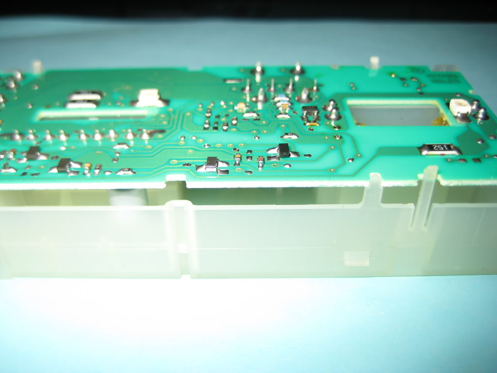
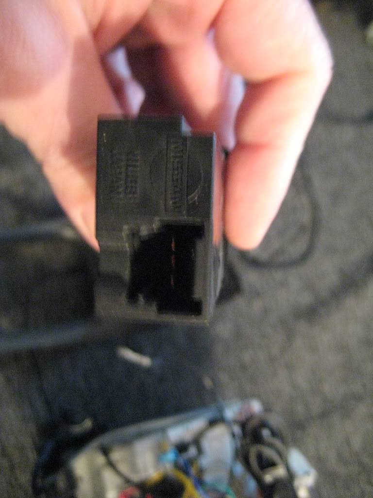
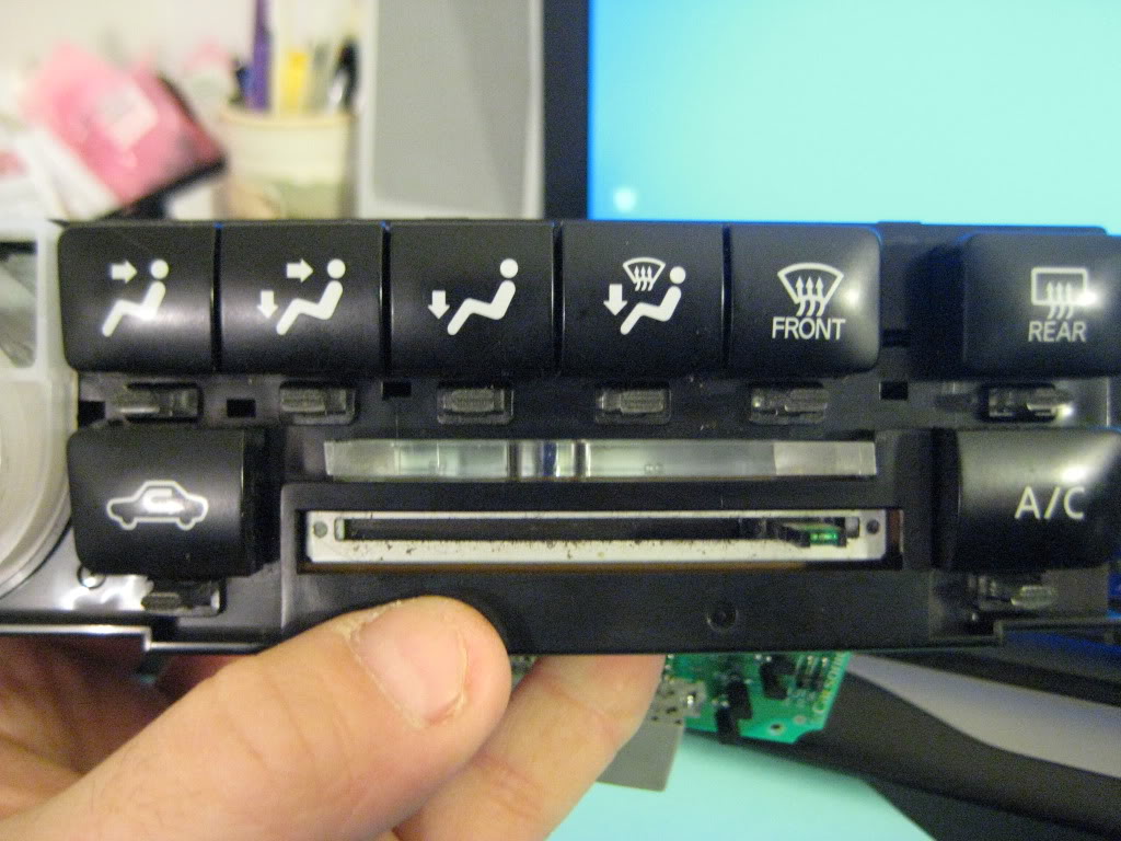
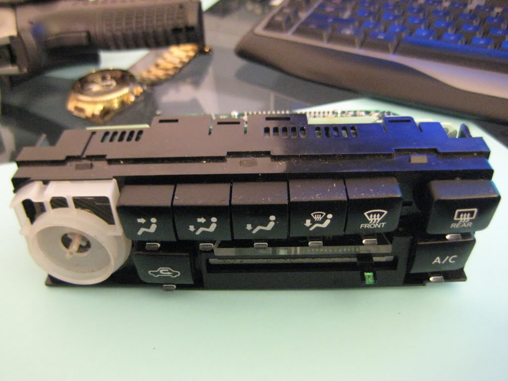
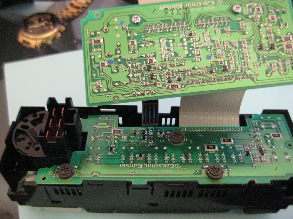
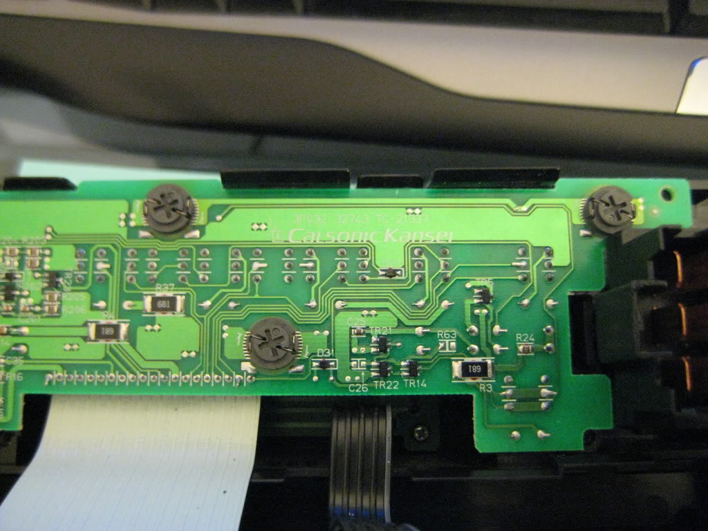
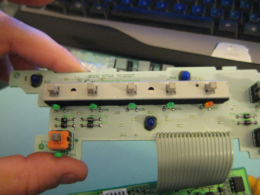
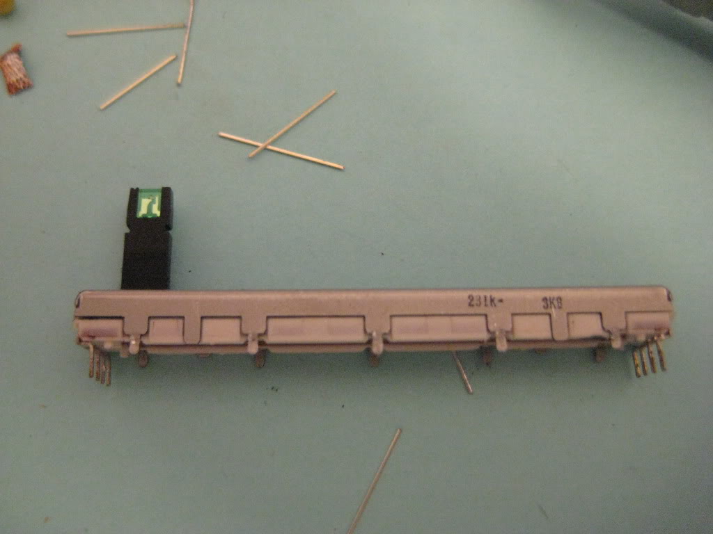
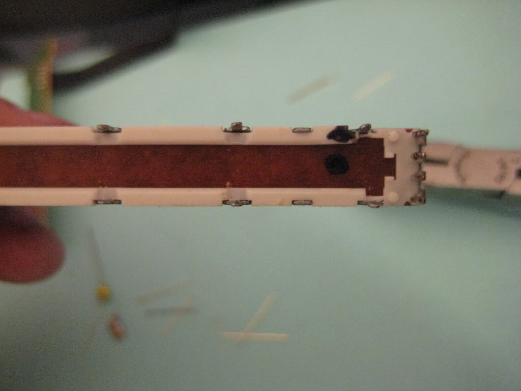
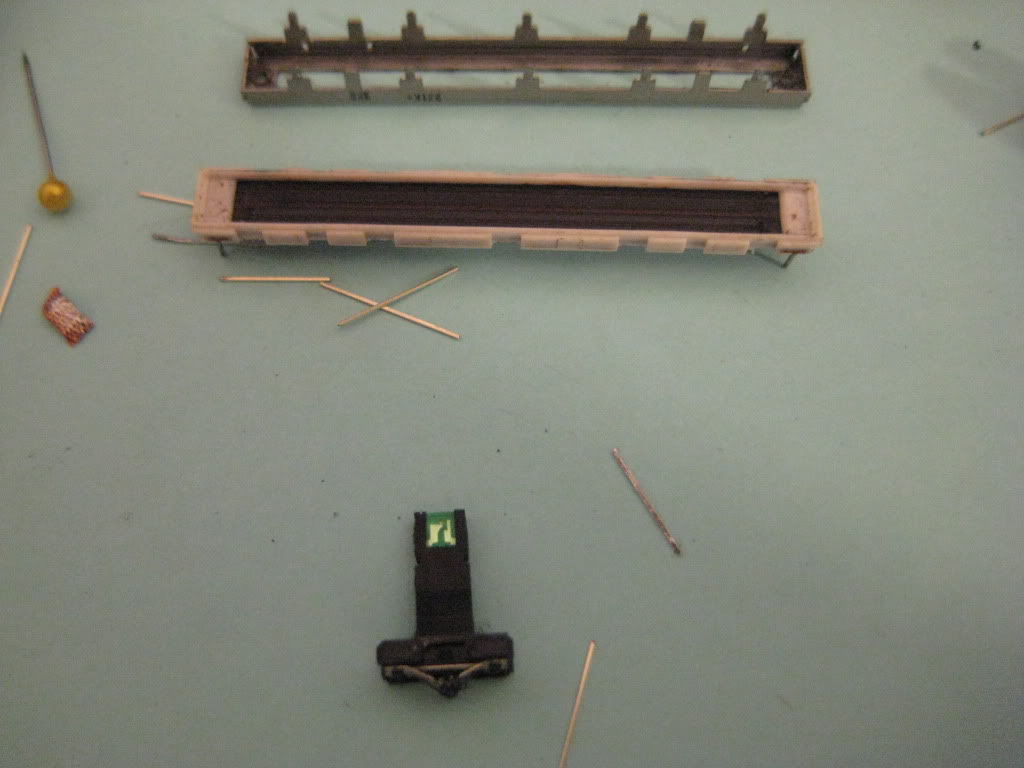
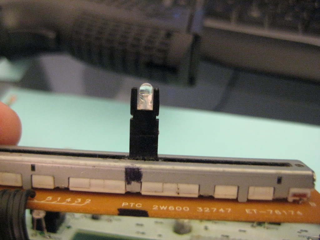
Remove and Disassemble A/C unit take care to pay attention to how everything goes back together.if you are replacing the 8 small led's like i have done take note of the lead placement before desoldering them all.now would be a good time to also unplug and remove the hot/cold slider.remove all 3 bulb sockets and then start to unsolder the smaller led's on the first row for the buttons the very last led on the right will give you problems both soldering and unsoldering because it is soldered to a large copper ground trace and it is going to act like a heat sink i just cut it and used some needlenose and heated it up to pull it out.now for the slider you can replace this with a 3mm led you will have to take a small file and shape it to fit.you do not have to disassemble the slider like i did i found this out after the fact you can pull the green led straight out it is not soldered or in a holder.just make sure you cut the leads on the new led slightly longer because the new led is not going to slip back into the holder completly.now for the pictures if there are questions about any of the steps please feel free to ask here or PM me for details.
Products Used: superbrightleds.com
(8) RL3-W6045 3mm White Led's
(3) NEO4-WHP 4mm Instrument Cluster Led's White
(1) RL-3B2030 3mm Blue Led
Remove and Disassemble A/C unit take care to pay attention to how everything goes back together.if you are replacing the 8 small led's like i have done take note of the lead placement before desoldering them all.now would be a good time to also unplug and remove the hot/cold slider.remove all 3 bulb sockets and then start to unsolder the smaller led's on the first row for the buttons the very last led on the right will give you problems both soldering and unsoldering because it is soldered to a large copper ground trace and it is going to act like a heat sink i just cut it and used some needlenose and heated it up to pull it out.now for the slider you can replace this with a 3mm led you will have to take a small file and shape it to fit.you do not have to disassemble the slider like i did i found this out after the fact you can pull the green led straight out it is not soldered or in a holder.just make sure you cut the leads on the new led slightly longer because the new led is not going to slip back into the holder completly.now for the pictures if there are questions about any of the steps please feel free to ask here or PM me for details.
 02-03-2012, 10:07 AM
#59
Senior Member
Thread Starter
iTrader: (4)
Join Date: Jul 2006
Location: Ontario, Canada
Posts: 5,548
Ugh manual climate control is SO much easier, that's crazy. thanks dude!
I've never touched a Hazard switch. Oldschool push button switches are about a 50% fail rate upon reassebly (if I were to randomly put a number on it), they're just a PITA, and are likely to screw up down the road once you mess with them. Just my $.02
Also, I have never seen a reason to touch it on the 5th gen. I did my 4th gen though.
The 5th gen's ACC has 2 red indicators for defrostrear/def front, also my auto has a red indicator for gear location, it all blends well with the red hazard. Also, IIRC, you can't take the red tint off most hazard swithces, not sure about the 5th gen though. Because of this, taking it apart is even more pointless cause you can't even change the colour.
Perhaps the 5th gen is different though?
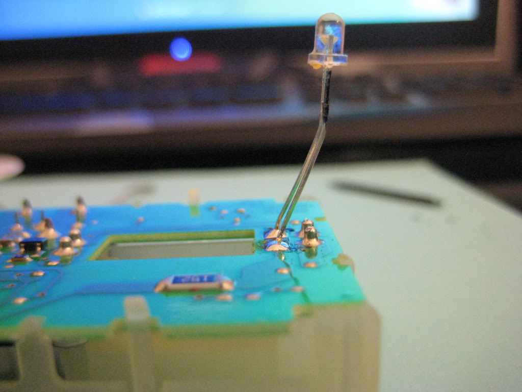
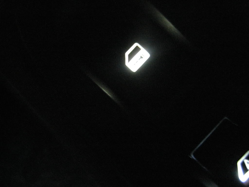
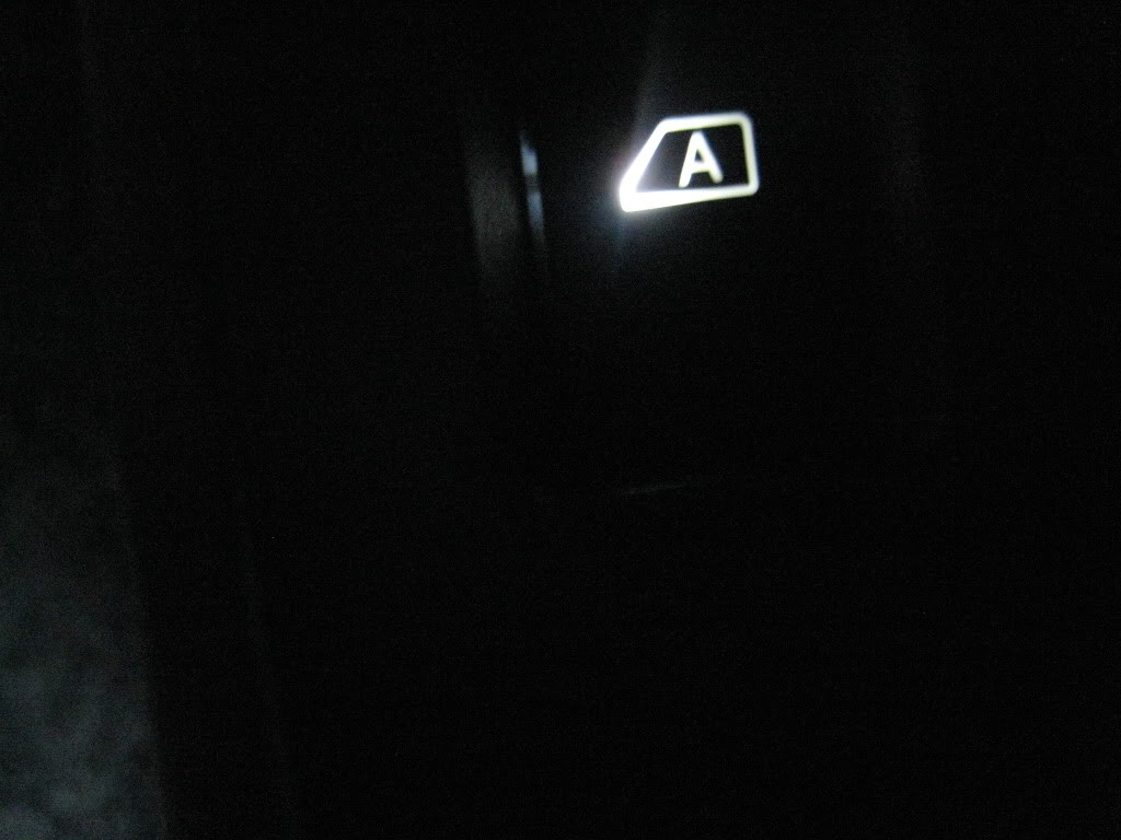
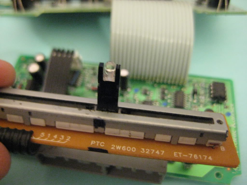
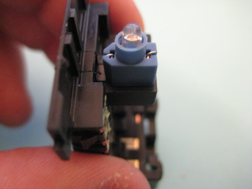
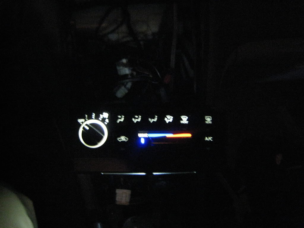
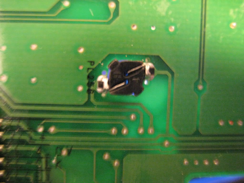
To the Dimmer, I need a pic, because I did not run into any problems, mine looks great and the LED i put in there is bright as *****, very crappy pic but you can see the dimmer at least:

I've never touched a Hazard switch. Oldschool push button switches are about a 50% fail rate upon reassebly (if I were to randomly put a number on it), they're just a PITA, and are likely to screw up down the road once you mess with them. Just my $.02
Also, I have never seen a reason to touch it on the 5th gen. I did my 4th gen though.
The 5th gen's ACC has 2 red indicators for defrostrear/def front, also my auto has a red indicator for gear location, it all blends well with the red hazard. Also, IIRC, you can't take the red tint off most hazard swithces, not sure about the 5th gen though. Because of this, taking it apart is even more pointless cause you can't even change the colour.
Perhaps the 5th gen is different though?
To the Dimmer, I need a pic, because I did not run into any problems, mine looks great and the LED i put in there is bright as *****, very crappy pic but you can see the dimmer at least:
02-03-2012, 10:42 AM
#60
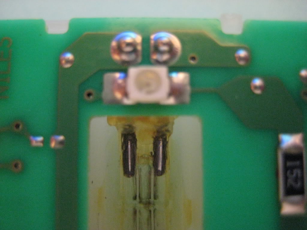
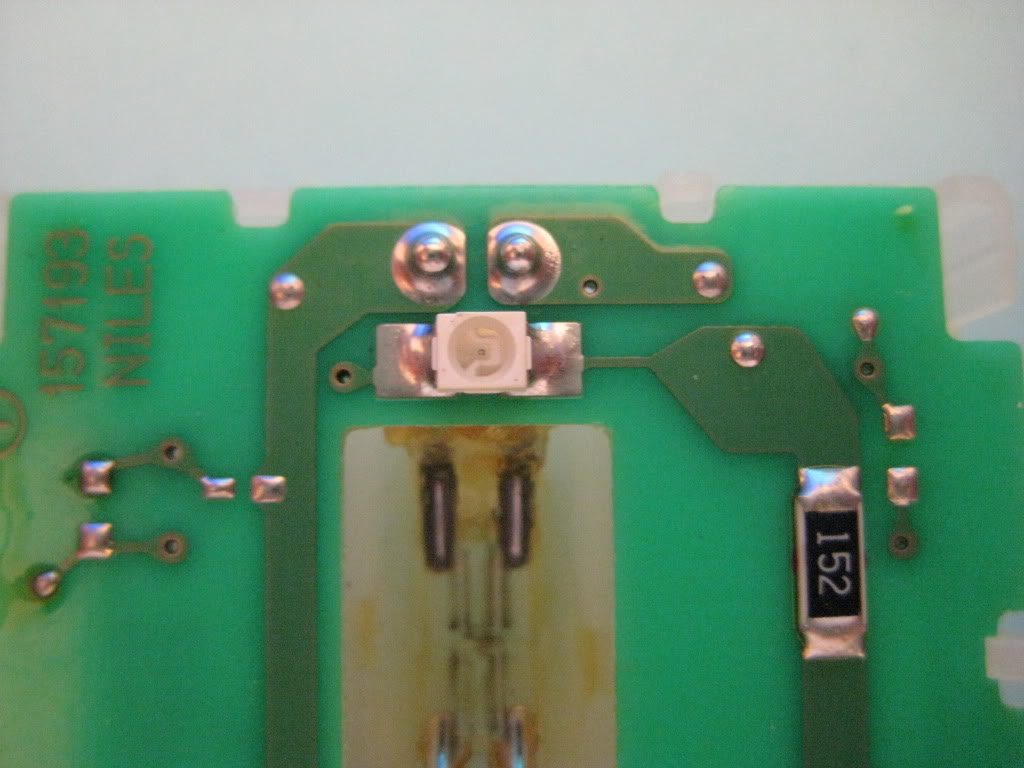
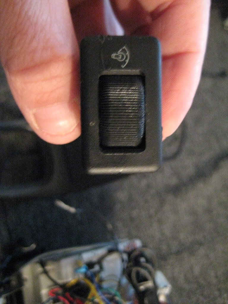
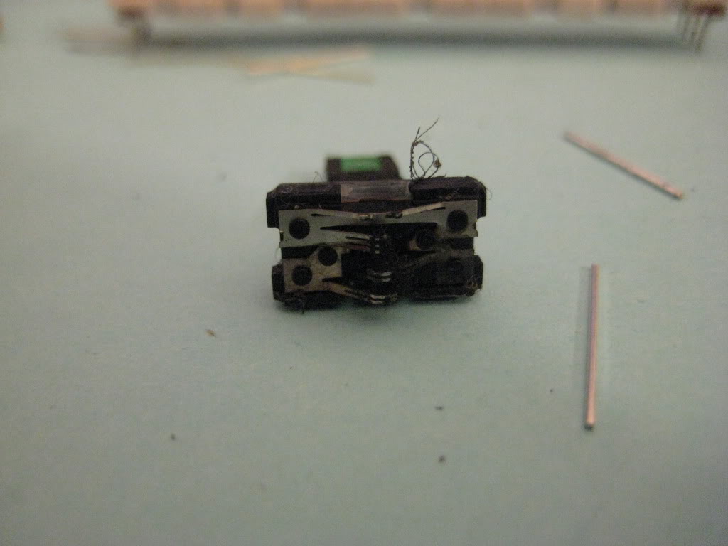
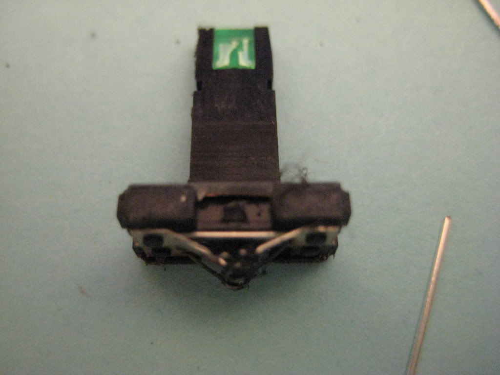
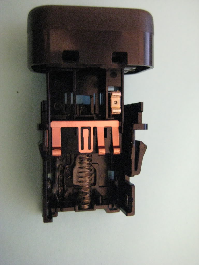
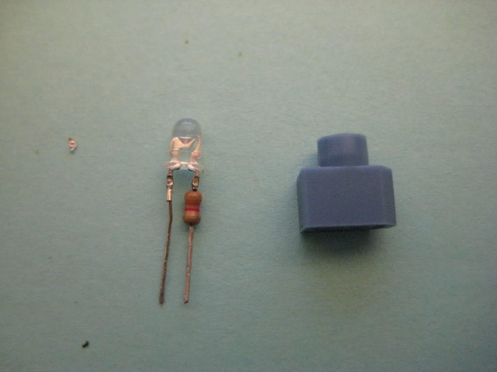
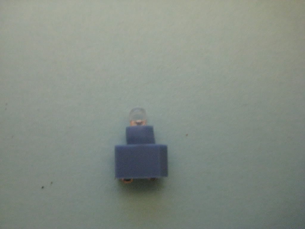
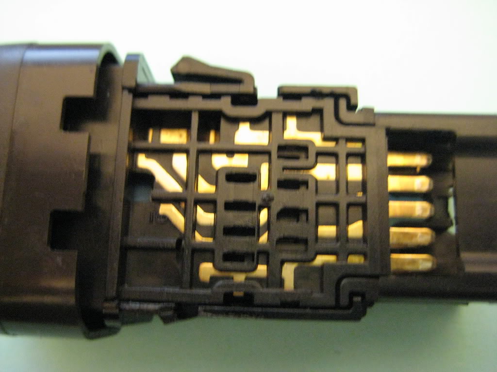
Hazzaed Switch:Caution Do This At Your Own Risk!!!!
Remove and disassemble switch be careful the spring will shoot out!
Led holder is the same as rear door switch as posted above just take note of where the resistor goes when putting the holder back into the assembly
Putting it back together is going to take patients because the spring has alot of tension on it just TAKE YOUR TIME.
02-03-2012, 11:32 AM
#61
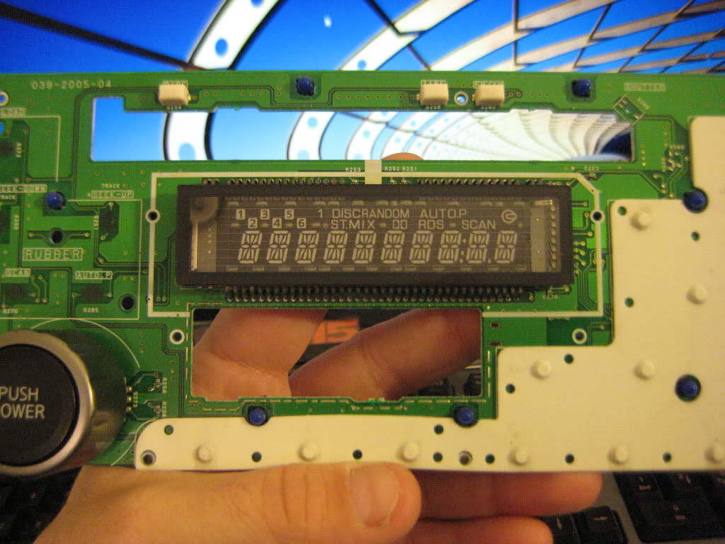
If anyone wants to see the OE Factory radio done let me know and i will also do that.My cluster will be done last as it needs to be cleaned up and if that does not work i will have to replace the clear plastic front.
02-03-2012, 01:56 PM
#62
Senior Member
Thread Starter
iTrader: (4)
Join Date: Jul 2006
Location: Ontario, Canada
Posts: 5,548
Is there really any difference in the Hazard switch? I still don't see the point.
The radio would be a great addition, as I never even attempted that either (aftermarket screen)
The radio would be a great addition, as I never even attempted that either (aftermarket screen)
02-03-2012, 02:18 PM
#63
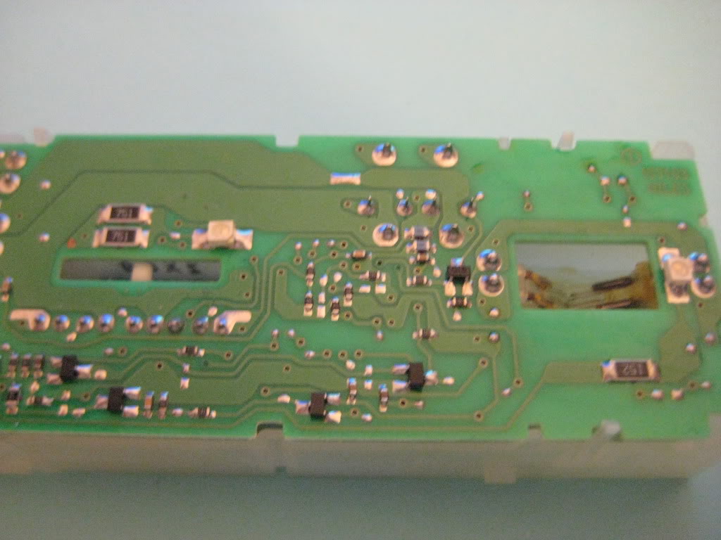
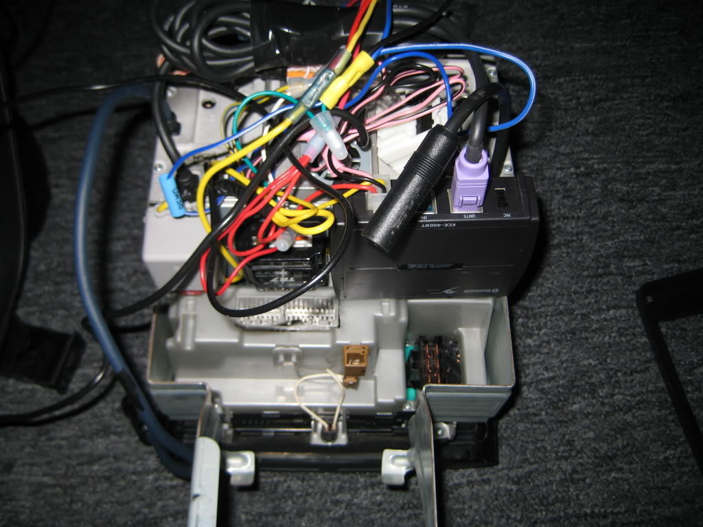
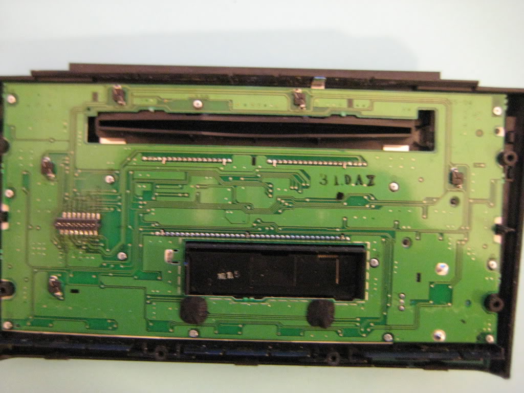
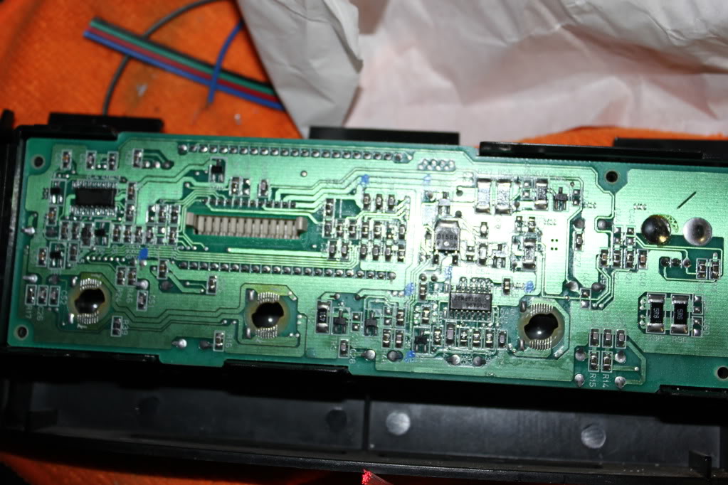
I pulled the radio apart it looks like 8 mini bulbs soldered to the board in holders not hard just need to find something small to replace them ill snap some pics of the board when i get home.
 02-03-2012, 05:27 PM
#67
Senior Member
Thread Starter
iTrader: (4)
Join Date: Jul 2006
Location: Ontario, Canada
Posts: 5,548
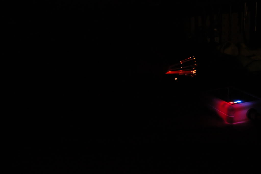
Cell phone cam?
Wow dude, I dont even know what's going on in those pics, just a flash of light. I don't even see the dimmer logo/tint piece that is supposed to be on there, as shown in my crappy picture above.
Keep a backlight on (dome light maybe?) and snap a photo so I can actually see somenthing.
P.S. I'm gitty like a school child for the newest plan of mine in this department. Ima post a pic or two here maybe later tonight cause I really feel I'm opening this game up so much....
02-03-2012, 05:35 PM
#68
No that is a from a Nikon l120 camers the led is that bright! it is literaly blinding its so bright you can see the outline of the white inlay(the line and box outline under the bulb symbol) as for the radio how about mounting some 5050 smt from the back side of the board to shine thru the opening for the bulb? im just kicking ideals around with it for now.any other parts you want me to open up and experiment with? the 03 and 97 are not moving for a while due to complete teardown of the front end on the 97 and the 03 lower part of the bumper broke in half because my neise put her feet in the 2 slots and stood up breaking it right in the middle.
 02-03-2012, 10:32 PM
#70
Senior Member
Thread Starter
iTrader: (4)
Join Date: Jul 2006
Location: Ontario, Canada
Posts: 5,548
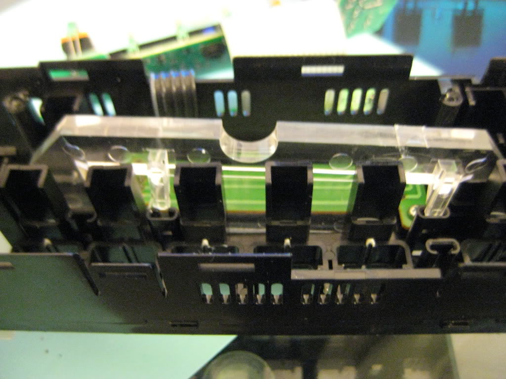
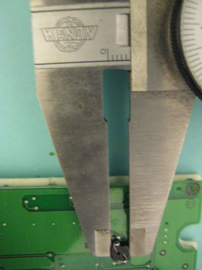
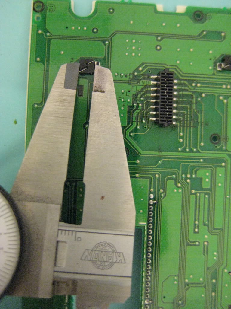
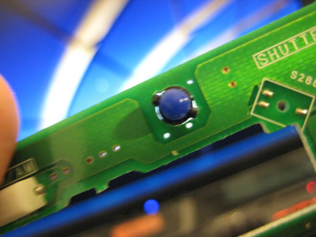
A 5050 SMD in the center of each cutout will work perfectly with no hotspotting. One for each button. Only one for the Fan also, in the center. Only downfall to this is you DO have to remove the circuit board/fully disassemble. Not hard, just be careful. This pic shows how perfect a 5050 fits:

And this is Matty Playing with new ideas

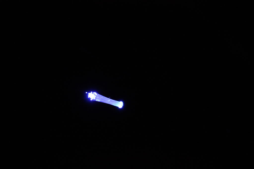
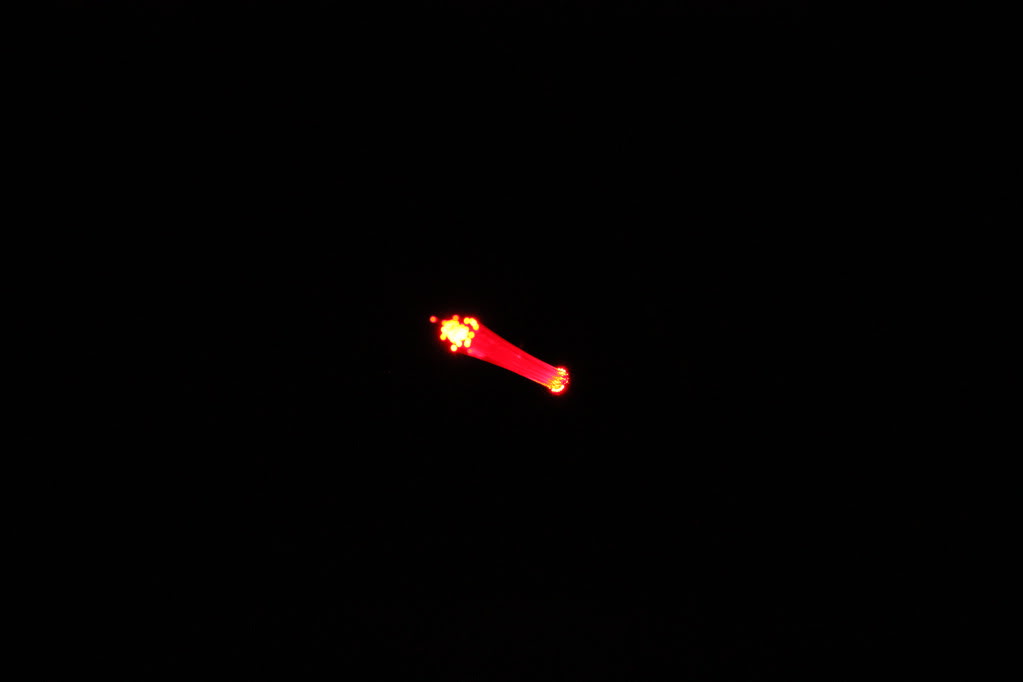

Here's a very small amount of Fiberoptic strands placed into a blacked out sidemarker lens. Imagine the possibilites for lighting. CCFL halos? Nah, LED halos? Yes, but with Side emitting Fiberoptic, much cheaper, and withthe visual appeal of CCFL but without the reliability issues that CCFL has
This is so bomb: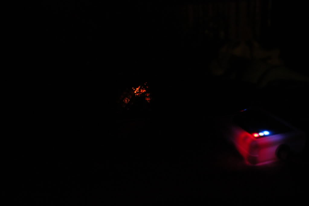
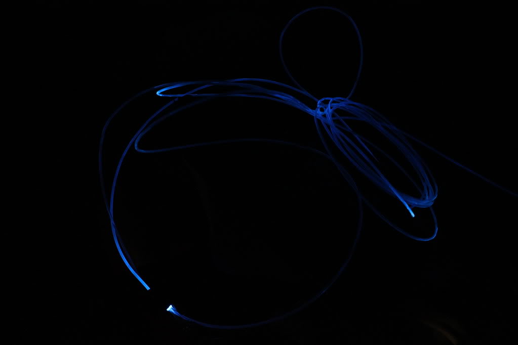
This is them laying flat on the inside of the lens. I contemplate running them all around the lens like this, sharp, flat:
Using this, you can install ligihting ANYWHERE, places you never thought you'd get a light. And it's not conductive, so you can just put it where ever and not have to worry about it, the light source can be mad far away. I am happy to add this to my arsenal
02-03-2012, 10:37 PM
#71
Senior Member
Thread Starter
iTrader: (4)
Join Date: Jul 2006
Location: Ontario, Canada
Posts: 5,548
No that is a from a Nikon l120 camers the led is that bright! it is literaly blinding its so bright you can see the outline of the white inlay(the line and box outline under the bulb symbol) as for the radio how about mounting some 5050 smt from the back side of the board to shine thru the opening for the bulb? im just kicking ideals around with it for now.any other parts you want me to open up and experiment with? the 03 and 97 are not moving for a while due to complete teardown of the front end on the 97 and the 03 lower part of the bumper broke in half because my neise put her feet in the 2 slots and stood up breaking it right in the middle.
02-04-2012, 06:41 AM
#72
man that fiber lighting is crazy.and yeah im going to have to work on the dimmer a bit i just dont understand why the damn thing is so damn bright it puts out more light then anything else.is there a way to mute the output by maby putting in a higher value resistor?well another thing i have been thinking about is back when i was working at Smith Industries aerospace they made this led indicator HUD overlay for a product it was like only 6-8 very small smt's with wire traces that were in clear plastic abot the thickness of paper that slid between the glass and display maby a design like that could be used for the instrument clusters.
02-04-2012, 06:50 AM
#73
Senior Member
Thread Starter
iTrader: (4)
Join Date: Jul 2006
Location: Ontario, Canada
Posts: 5,548
man that fiber lighting is crazy.and yeah im going to have to work on the dimmer a bit i just dont understand why the damn thing is so damn bright it puts out more light then anything else.is there a way to mute the output by maby putting in a higher value resistor?well another thing i have been thinking about is back when i was working at Smith Industries aerospace they made this led indicator HUD overlay for a product it was like only 6-8 very small smt's with wire traces that were in clear plastic abot the thickness of paper that slid between the glass and display maby a design like that could be used for the instrument clusters.
 You got it dude, just up the resistance to lower the output. 470k, 560k, 640k are the most common 1/4 watt resistors. I assume you're using a 470 so try the 640 and re aim.
Regarding the paper tracer wire idea, I'm going to need that for the window switches, etc when I do the RGB's inthere, I'm not sure where to get it though, need a strip of 3. Thought about robbing some old ribbon stuf from an old computer or something, what do you think?
As far as under the needles, this is a good idea, but any circuit board/flat LED jobs I've seen are always hotspotted to hell. some people like that though, I just dont personally. Aiming the LED/SMD directly at the gauge will cause hotspots or more work to get rid of them/redirect the light. No point in doing this when you can just redirect the light fromthe start and place it at a 45-90 degree angle tot he gauge face.
Just popthat dimer apart and post pics, either way,something doesnt seem right dude.
02-04-2012, 07:18 AM
#74
Ding ding ding, winner You got it dude, just up the resistance to lower the output. 470k, 560k, 640k are the most common 1/4 watt resistors. I assume you're using a 470 so try the 640 and re aim.
Regarding the paper tracer wire idea, I'm going to need that for the window switches, etc when I do the RGB's inthere, I'm not sure where to get it though, need a strip of 3. Thought about robbing some old ribbon stuf from an old computer or something, what do you think?
As far as under the needles, this is a good idea, but any circuit board/flat LED jobs I've seen are always hotspotted to hell. some people like that though, I just dont personally. Aiming the LED/SMD directly at the gauge will cause hotspots or more work to get rid of them/redirect the light. No point in doing this when you can just redirect the light fromthe start and place it at a 45-90 degree angle tot he gauge face.
Just popthat dimer apart and post pics, either way,something doesnt seem right dude.
You got it dude, just up the resistance to lower the output. 470k, 560k, 640k are the most common 1/4 watt resistors. I assume you're using a 470 so try the 640 and re aim.Regarding the paper tracer wire idea, I'm going to need that for the window switches, etc when I do the RGB's inthere, I'm not sure where to get it though, need a strip of 3. Thought about robbing some old ribbon stuf from an old computer or something, what do you think?
As far as under the needles, this is a good idea, but any circuit board/flat LED jobs I've seen are always hotspotted to hell. some people like that though, I just dont personally. Aiming the LED/SMD directly at the gauge will cause hotspots or more work to get rid of them/redirect the light. No point in doing this when you can just redirect the light fromthe start and place it at a 45-90 degree angle tot he gauge face.
Just popthat dimer apart and post pics, either way,something doesnt seem right dude.
to think about it now i could probly grab some clear contact paper the sticky stuff and show you what i mean but then again the clear contact paper might just work good too.use a clear sheet protector with holes punched for the locations wire it up with some single strands of wire and cover with the clear contact paper.
Last edited by cjandura; 02-04-2012 at 07:22 AM.
02-04-2012, 07:57 AM
#75
My wife just gave me a ideal sence im rummaging thru her office for stuff.she said to try one of them self laminating ID pouched from staples that would work its sticky on one side only and semi thicker then paper.
02-04-2012, 08:00 AM
#76
Home made trace may be found check these links
http://www.mgchemicals.com/products/8420p.html
http://www.mgchemicals.com/products/pens.html
http://www.mgchemicals.com/products/8420p.html
http://www.mgchemicals.com/products/pens.html
02-04-2012, 02:42 PM
#78
Looks good. I have heard that there is a different process for the different master switches. Notice yours has the "A" on the front window switches and my 02 does not. I also notices you have the equal sized lock and lockout bottons. Someone confirm if the different switches require special methods.
02-06-2012, 10:00 AM
#79
The link for the 360 LEDs from superbright LEDs is:http://www.superbrightleds.com/cat/c...le,181,39,360: and as for execution on how to use them. Just get some 5mm 360 LEDs use a 620 OHM 1/8 Watt resistor and a 1N4148 fast switching diode and use you stock neo wedge bases for your climate control.
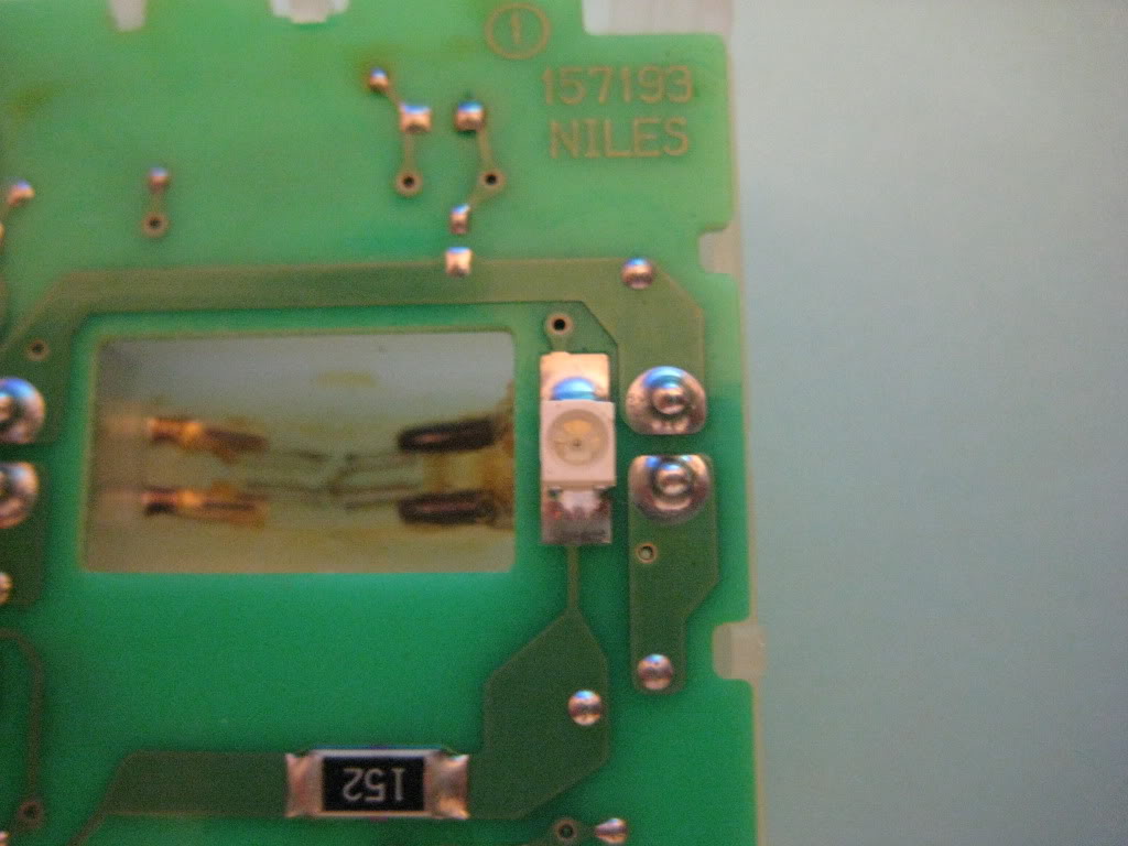
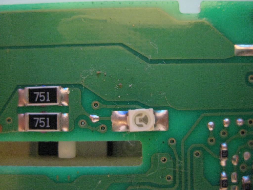
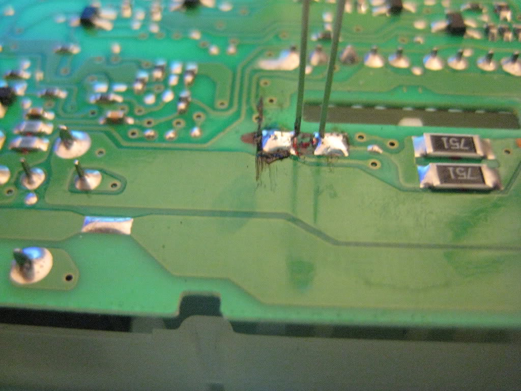
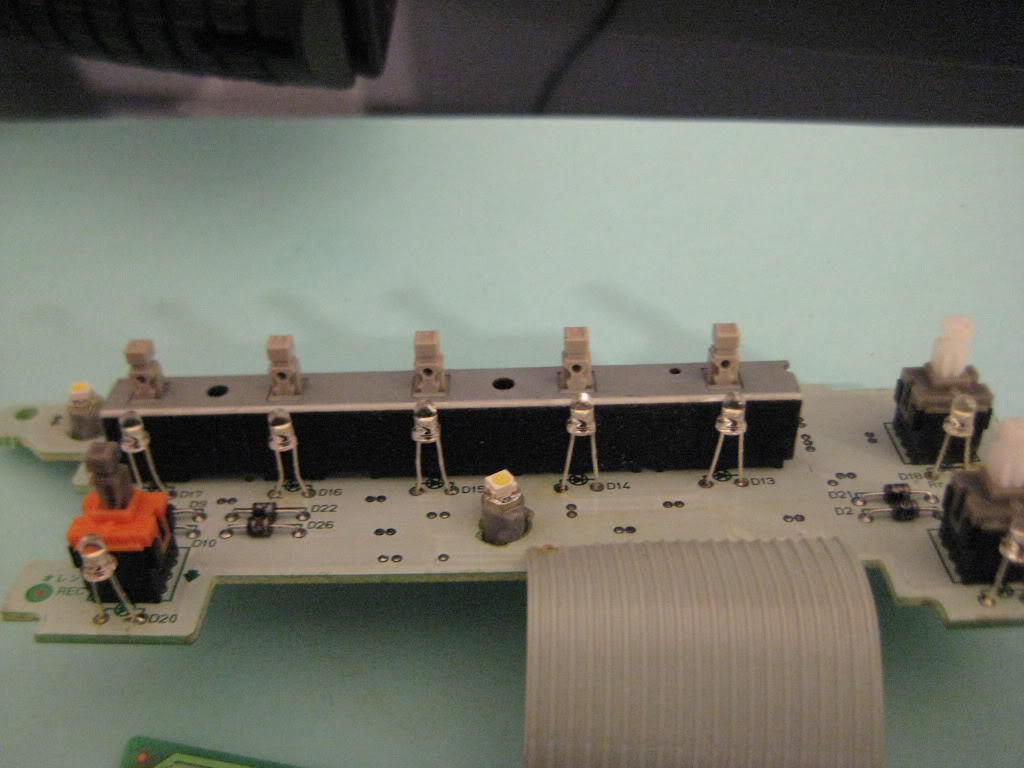
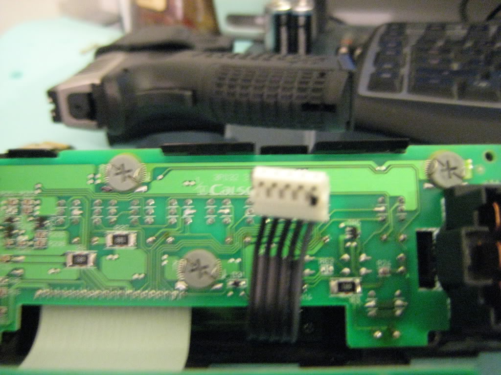
As for your Radio you will have to remove your stock bulbs using desoldering braid or a suction style desolderer. then just solder the LEDs with resistors directly to the board like so: (Was my first time so I had to repair some damage I did to the board so that is why you see some grey strips at certain points)


Just remember on the back of the circuit board the anode (+) is below each bulb and the cathode (-) is above the bulb. On the volume **** the anode is on the right and the catode is on the left. Also, when attaching diode and resistor to the LED the long lead is the anode and that is where you attach the resistor and the cathode is the short lead and that is where you attach the switching diode.
As for your Radio you will have to remove your stock bulbs using desoldering braid or a suction style desolderer. then just solder the LEDs with resistors directly to the board like so: (Was my first time so I had to repair some damage I did to the board so that is why you see some grey strips at certain points)
Just remember on the back of the circuit board the anode (+) is below each bulb and the cathode (-) is above the bulb. On the volume **** the anode is on the right and the catode is on the left. Also, when attaching diode and resistor to the LED the long lead is the anode and that is where you attach the resistor and the cathode is the short lead and that is where you attach the switching diode.
02-06-2012, 10:05 AM
#80
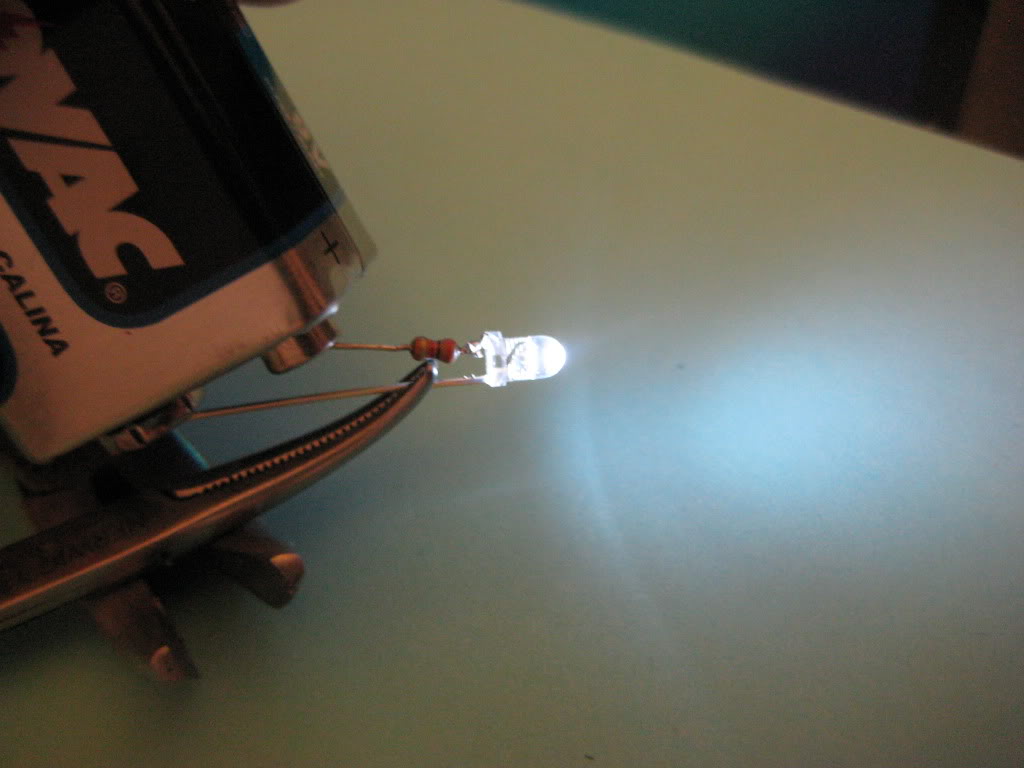
This is a picture of a 5th gen LED mini strip using 4 white 0.5 Watt 360 LEDs for a 5th Gen. Using basic run of the mill stripboard and a 39 OHM 1/2 Watt resistor a T15 Wedge Base and a 1N4936 rectifier diode(for reverse polarity protection)

And the lights in action

And the lights in action
Last edited by Shinjiduo; 02-06-2012 at 10:08 AM.