LED tails......pics are up!!!
 02-09-2006, 05:49 PM
#1

LED tails......pics are up!!!
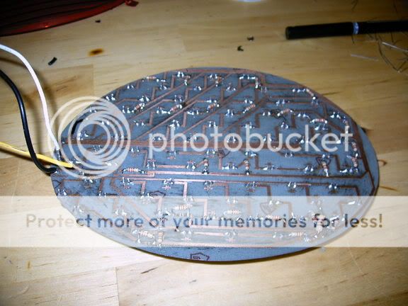
finaly got the 1st board done, figure i would post some pics. i still need to make up the second board and get the panels into a good set of tail lights. will update when i do.
Back
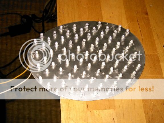
Front
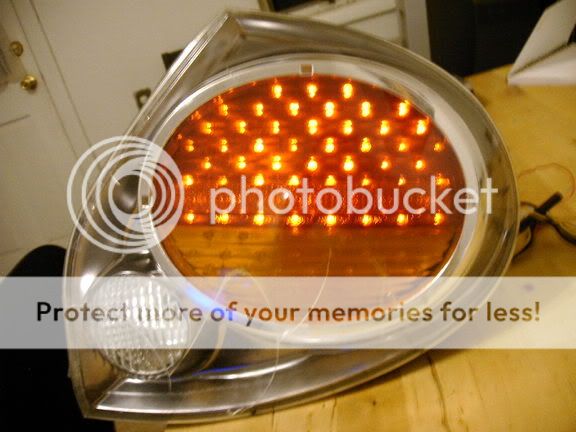
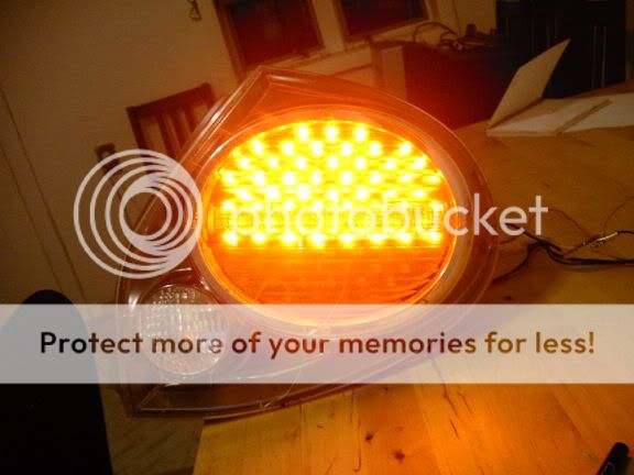
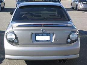
This is what they look like in a busted up 5.5 gen taillight
Tailights
Back
Front
This is what they look like in a busted up 5.5 gen taillight
Tailights


 02-09-2006, 06:17 PM
#9
Oh shyt that is sweet. I want a pair. How much did parts cost you? Will a resistor be necessary to prevent hyperblink and/or burned out tail light notice? I'm sure a ton of people would be interested in buying these. Count me in for sure.


 02-09-2006, 07:00 PM
#15
that looks really good so far. how are they during the day time? my friend retrofited led in his accord and during the day you can't even see if brakes are on or not but during night they're brighter. i have a feeling these are going to be pretty good during daytime cuz the leds are pretty big.

 Wow. Great workmanship on the board!


 02-09-2006, 09:09 PM
#30
Supporting Maxima.org Member

iTrader: (8)
Join Date: Dec 2005
Location: Atlantic City, NJ
Posts: 606
Very Very sic job....... and you find time to do this when??? in between chapters in your clinical pharmacology book 
by the way how did you do those perfectly straight copper contacts? is that painted on?
by the way how did you do those perfectly straight copper contacts? is that painted on?
02-09-2006, 10:48 PM
#31
Newbie - Just Registered

Join Date: Dec 2005
Posts: 10
Hmmm...it looks to me like chemically-etched copper. Must have taken a while to create the mask for it, though. Good job!!
I'm working completely on assumptions, but from the first picture, could you verify if these are correct (just out of interest):
You have a top and bottom array of LEDs. Each is (independently) in series
The car supplies two voltages - brake (high) or normal lights (low) to the top array
A separate voltage ('high') is applied to the 'signal' array (bottom)
Is there a particular reason why you placed resistors across each diode (LED), as opposed to simply current-limiting each supply lead?
Thanks - if you share some of the 'inside' secrets, maybe you could help some other brave do-it-yourselfers...

 . Again GREAT work


